
Fluid power Fluid power systems transfer and utilize mechanical power through a working fluid. Energy is transmitted, stored and used through the transfer and pressure of fluids. There are two main types of fluid power system: Hydraulic – using liquid, such as oil, for the working fluid Pneumatic – using gas, such as air, for the working fluid
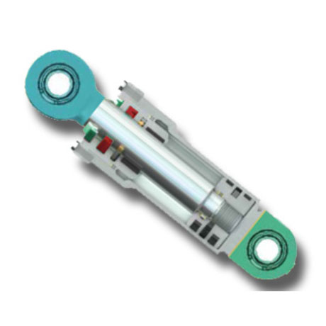
Designing sealing and guide systems in hydraulic cylinders requires careful attention to the interaction between all cylinder components and the operating conditions as well as the application requirements. Sealing systems are important because they keep the fluid media and the system operating pressure in and contaminants out of the cylinder. Guide rings provide effective guidance of components that are in relative motion to each other and accommodate radial loads acting on the cylinder assembly. The selection of the right seal and guide for a given application requires consideration of many factors. Therefore, SKF manufactures and sells hydraulic seals and guides in many different profiles, materials and in a wide range of series and sizes, which make them appropriate for a wide variety of operating conditions and applications. Each of these designs and material combinations has specific properties, making them suitable for a particular application.
This section and its sub-sections provide the necessary basic information. It starts with an overview over hydraulic cylinder types and classification, and an introduction to seal and guides with their functions. Furthermore, technical information such as seal counter-surface finish properties, materials, fluid media and gap extrusion are discussed in detail. Product storage and installation is included as well. The seal type sections provide type and profile specific information and characteristics are discussed in detail too.
Obviously, it is impossible to include all the information needed to cover every conceivable application. If application requirements are not served by the common profiles or sizes in these sections, contact SKF for additional information and for providing a specific offer. For any application factors outside of the ordinary, or to specify sealing systems in new hydraulic cylinder designs, a certain amount of expertise, beyond the content of this section, may be required. The hydraulic seal experts at SKF can assist in selecting the right sealing system for new cylinder designs.
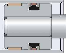
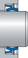
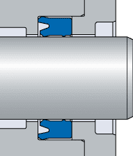
Colour coding for materialThe product illustrations in the following sections use a colour coding system to indicate the material group (table 1), but they do not match the actual material colours. For information about the actual material colours, refer to Materials.
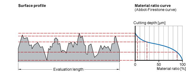
The surface properties of the cylinder bore and the piston rod have a great influence on the function and service life of the seal. Parameters for specifying a surface finish are defined by ISO 4287:1997. The most common surface roughness parameter specified is Ra (in units μm or μin.), i.e. the arithmetic mean deviation of the surface profile. This value does not, however, completely describe how the surface can be expected to affect the seal. The reason for this is that two surfaces with the same values of Ra but with different surface profile characteristics can lead to different lubrication film thickness, resulting in varying seal performance and level of wear.
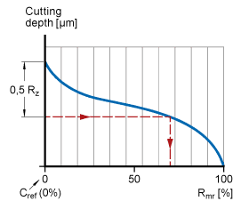
The material ratio curve (Abbott-Firestone curve) provides more information about the surface profile characteristics. It describes the ratio of the material-filled length to the evaluation length at a given cutting depth expressed in percent (fig. 1). The slope at the beginning of the curve represents the peaks in the profile, which are causing initial wear on the seal. The slope at the end of the curve represents the valleys in the profile, which serve as lubricant reservoirs.
Table 1 shows some surface profiles. To select a surface finish with a suitable profile and characteristics for effective dynamic sealing, SKF recommends a defined combination of the following surface parameters:
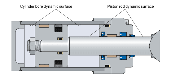
The dynamic sealing surfaces on the piston rod and in the cylinder bore (fig. 1) require similar, but somewhat different surface finishing.
Piston rodThe recommendations for the piston rod sealing surface (table 1) assume that typical materials and processes are used to manufacture the piston rod by induction hardening a carbon steel rod, grinding, hard-chromium plating and then polishing it to achieve the specified diameter and finish.
For alternative rod materials and coatings, other surface specifications, finishing methods, seal materials and designs may be required. Examples of such alternative rod coatings include:
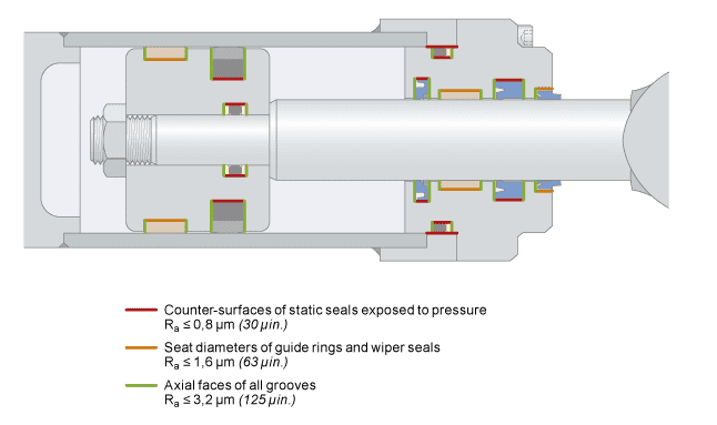
Static sealing surfaces must also have a proper surface finish to enable the desired sealing performance (fig. 1).
The counter-surfaces of static seals exposed to pressure, including the static side of dynamic rod and piston seals, should have a roughness Ra ≤ 0,8 μm (30 μin.).
Seat diameters of guide rings and wiper seals should have a roughness of
Ra ≤ 1,6 μm (63 μin.). Axial faces of all grooves should have a roughness of
Ra ≤ 3,2 μm (125 μin.).
Materials play a major role in the performance and lifetime of seals. Generally, hydraulic seals are exposed to a variety of application and working conditions, such as a wide temperature range, contact with various hydraulic fluids and the outside environment as well as high pressures and contact forces. The appropriate seal materials have to be selected to achieve a reasonable service life and service intervals. A wide variety of seal materials from four major polymeric material groups is available:
Many different material properties should be considered to support and maintain the sealing function over the expected seal service life, for example:
In addition to these considerations, the structure and morphology of polymeric materials make selection and specification of seal materials much more complicated than the standard materials used in mechanical engineering (e.g. aluminium or steel). Mechanical properties of polymeric materials are strongly influenced by time, temperature, load and rate of motion. Highly complex intermolecular processes affect the stress relaxation and retardation phenomena. Furthermore, the tribology conditions of the system (e.g. friction and wear) has a strong influence on the seal material behaviour and vice versa. Therefore, state-of-the-art sealing systems can only be developed by close cooperation between material experts and product designers, supported by advanced design tools like non-linear FEA and extensive seal testing capabilities.
SKF has a global material development organization that closely cooperates with the product development and testing functions. SKF is uniquely suited to develop, simulate, test and manufacture tailor-made materials for specific customer needs.
The tables in the following sections list the most common materials used by SKF for serial production of hydraulic seals. A wide variety of additional seal materials are available for special hydraulic seals or other seal applications.
SKF has a long history in developing and supplying special polyurethane grades for sealing purposes. SKF manufactures the well-known ECOPUR family of polyurethanes including H-ECOPUR for outstanding chemical and hydrolysis resistance, X-ECOPUR for extrusion resistance or S-ECOPUR for low friction and resistance to wear.
Polyurethanes combine the elastic properties of elastomers with the processability of thermoplastic materials. Seals made of polyurethanes provide excellent wear and pressure resistance and avoid leakage. Due to their elasticity and flexibility, they are easy to install. Special sealing polyurethane grades have a superior compression set and relaxation performance as well as temperature stability compared to commodity industrial grades.
Table 1 lists common thermoplastic elastomers.
Rubbers are widely used in the seals industry for rotary shaft seals, static sealing elements such as O-rings and energizers, as well as dynamic seals in the fluid power industry. Depending on the chemical composition, rubbers can cover a wide temperature range up to 200 °C (390 °F) and more and withstand a wide variety of hydraulic fluids. NBR elastomers in a hardness range from 70 to 90 Shore A (shA) are the most commonly used rubbers in the fluid power industry. For higher temperatures and more aggressive hydraulic fluids, SKF recommends HNBR or FKM elastomers.
Table 1 lists common rubbers.
At temperatures above 300 °C (570 °F) all fluoro elastomers and PTFE compounds give off dangerous fumes. If there is contact with your skin or if the vapours are inhaled, seek medical advice immediately.
At temperatures above 300 °C (570 °F) all fluoro elastomers and PTFE compounds give off dangerous fumes. If there is contact with your skin or if the vapours are inhaled, seek medical advice immediately.
Fluids used in hydraulic systems serve multiple functions for the system performance:
Transfer power by flow under pressure acting on moveable parts
Lubricate surfaces in contact and relative motion – hydraulic cylinder components and seals, as well as other system components such as pumps and valves
Prevent corrosion of components
Cool the system, by carrying heat from areas of high load, motion or turbulence and spread it to the entire volume of the system including reservoir tanks and cooling equipment
Clean the system by carrying contaminants and wear particles to filter bodies or settling areas
The fluids used in hydraulic systems come in various chemical compositions and viscosity grades as suited to specific applications.
Viscosity is a measurement of the thickness of a fluid or the resistance to flow. Seal performance is affected by the viscosity of the fluid and changes to the viscosity during use. Most typical hydraulic fluids exhibit decreased viscosity with increasing temperature and increased viscosity with increasing pressure.
The most commonly used media in hydraulic systems are mineral oil based fluids with various additives. However, a variety of alternative fluids may be encountered in special applications. For example, biodegradable fluids such as synthetic (HEES) or natural esters (HETG) and polyalphaolefins (PAO) may be used to reduce environmental impact in the event of accidental spills. Flame retardant fluids based on water or synthetic esters may be safely used in confined spaces or where the hydraulic system is used in close proximity to ignition sources. The data, specifications and recommendations in this section are for common mineral oil fluids. For guidance on specifications of sealing systems for alternative fluids, contact SKF.
The chemical composition of hydraulic fluids can impact the seal life and performance depending on compatibility with the seal material(s). Absorption and reaction of the seal material(s) with non-compatible fluids can cause, for example:
Generally, these changes are accelerated by higher temperature. To avoid these changes and the resulting damage to seal function and life, careful consideration should be taken to enable compatibility between the fluid and all seal materials, as well as the temperature and mechanical loads on the seal material. SKF has a long history and extensive database of test results concerning compatibility of various seal materials and fluids, as well as unparalleled expertise in developing materials to meet customers’ needs for chemical resistance of seal materials.
Table 1 summarizes the compatibility rating for the most important fluids and materials used in the fluid power industry. For materials not listed, contact SKF. Table 1 provides general guidelines for new, clean fluids. Fluids vary by manufacturer, additives and contaminant levels. Materials vary by specific compound. The guidelines cannot substitute for testing the compatibility of a seal in the actual fluid and under actual operating conditions. Temperatures higher than specified in table 1 can lead to degradation of the basic fluid or its additives. This can cause deterioration of the seal material. For applications where higher temperatures are required, contact SKF.
In addition to the specified hydraulic fluid, seal materials can be attacked by exposure to other fluids from other parts of the machinery (e.g. greases, fuels, coatings), environmental factors (e.g. humidity or radiation) and degradation and reaction with the fluids, additives and contaminants in the system producing additional chemicals.
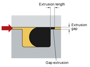
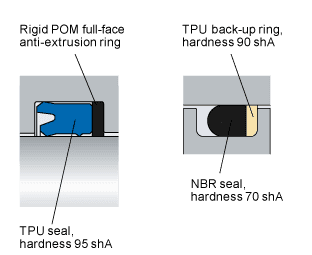
The resistance of a given seal component to gap extrusion is mainly determined by the material composition and quality. Materials of greater hardness and stiffness typically also have improved resistance to extrusion. Therefore, full-face anti-extrusion or back-up rings of materials harder than the seal material may be used to prevent seal extrusion into the e-gap.
Pressure is the main driver of extrusion, but the e-gap size and application temperature are also major factors. Diagram 1 shows the pressure resistance of different materials as a function of temperature. The values were measured on an SKF test rig. The tests were carried out with a rectangular sample, dimensions 38,7 x 49 x 5 mm under static pressure and an extrusion gap of 0,3 mm. The pressure values were taken at an extrusion length of 0,5 mm. While these sample values illustrate the differences in extrusion resistance for standard grades of typical seal materials, there are many variations of each basic composition that impact the extrusion resistance of seals. In addition, the profile design and the seal friction affect extrusion. For maximum allowable pressure, temperature and e-gap of each seal profile, refer to the profile data for each profile in the relevant sections.
The maximum e-gap in a hydraulic cylinder cylinder occurs when the cylinder components are at the maximum radial misalignment of components. This misalignment is affected by:
Therefore, it is necessary to calculate the e-gap at the maximum misalignment at minimum material conditions of the cylinder and guide components.
For rod seals, the maximum e-gap should be calculated with the following conditions:
For piston seals, the maximum e-gap should be calculated with the following conditions:
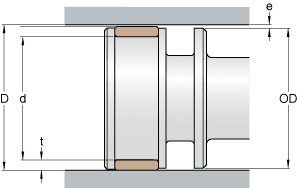
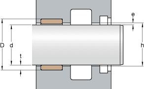
The maximum allowable e-gap is provided in the profile data for each rod seal and piston seal profile in the relevant section. The e-gap can be kept within these limits by specifying and controlling the tolerances of dimensions described above and shown in fig. 3 and fig. 4.
During storage, the properties of elastomer products can be damaged either by chemical reactions or by physical processes. Chemical reactions are basically caused by the influence of heat, light, oxygen, ozone or contamination by chemicals. The physical processes, which are called physical ageing, are either due to the influence of external stresses leading to cracks and permanent deformation, or due to the migration of plasticizers, which makes the material more brittle and can lead to deformation of the parts.
Therefore, elastomer products only maintain their characteristics for several years without major changes, if they are properly stored. The ageing behaviour of elastomer products and their reaction on storage conditions depend considerably on their chemical structure. Unsaturated elastomers (e.g. nitrile rubber) age more quickly under improper storage conditions than saturated elastomers (e.g. fluorocarbon rubber).
Elastomer products should be stored in accordance with the following recommendations, which are in line with the recommendations provided in ISO 2230:2002 or DIN 7716:1982.
When stored under the conditions mentioned above, elastomer products retain their typical properties for several years (table 1).
The typical shelf life may be prolonged based on the actual product conditions at the end of the typical shelf life. Trained and experienced experts can approve a prolonged storage period based on a visual inspection of representative samples. The samples should not reveal any permanent distortion, mechanical damage or surface cracking. The material should not show any signs of hardening or softening nor any kind of tackiness.
The type of seal housing determines the method of installation, required equipment and the degree of difficulty. There are four main types of seal housings.
Closed housing grooves are the most common seal housings. They require the most planning and effort that the seal is installed properly without damage. Not all seal cross section sizes and material combinations can be installed into this type of seal housing.
Open housing grooves allow the seal to be pressed in with minimal deformation and are therefore a good choice when the seal design, material or size prevent installation into a closed or stepped housing. Some seals, such as press-in wiper seals, have a metal sleeve that retains the seal in an open groove by press forces, whereas other seals may require a snap ring. Plastic snap rings, such as RI for rods or RR for piston, are available from SKF on request. Open housing grooves require specified edge radii or chamfers to prevent seal damage when the seal enters the housing groove or passes the snap ring groove.
These grooves incorporate two separable machine components to provide an open groove when the seal is installed and a closed groove when the machine is fully assembled.
Stepped grooves allow seals to be installed with less deformation. Snap-in wiper seals are a common example in hydraulic cylinder applications.

The corner radii inside the groove should be sized to avoid inadvertent contact with with the adjacent portion of the seal. Static side corner radius recommendations are provided in the size lists of the relevant product section.
All outside groove edges and any other edges that may come into contact with the seal during installation or use should be broken with a small radius. Otherwise, the sharp edge may damage the seal. Unless otherwise specified, all outside groove edges should have a radius of approximately 0,2 mm (0.008 in.).